




Inaccurate as-built drawings cost AEC firms real money on almost every renovation, retrofit, or historic preservation project. Manual field measurements seldom match true building conditions, and the gap only shows up once construction starts. A column ends up six inches off. A ceiling height gets rounded to the nearest foot. MEP engineers ask for exact clearances and get a guess instead. None of this surfaces until a contractor opens a wall and finds a duct where the drawing showed clear space, and the fix comes straight out of the project budget.
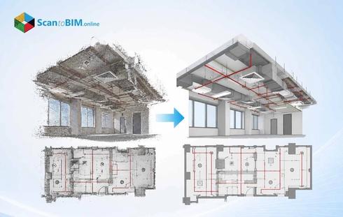
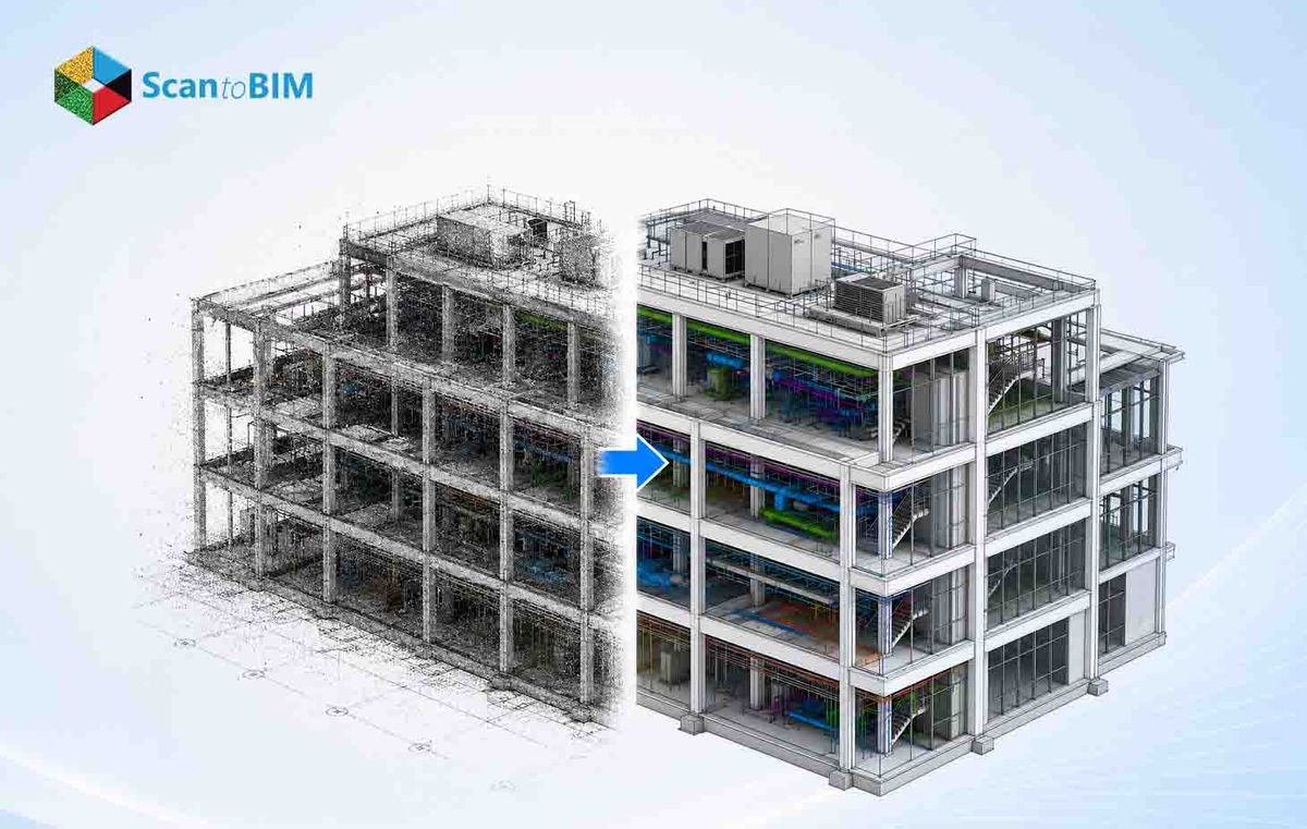
Point cloud to BIM removes that guesswork before construction starts. A laser scanner captures a building's real geometry as millions of coordinate points, typically within a few hours. BIM specialists then convert that data into a parametric Revit model built on actual measurements instead of field notes. Wall thicknesses, ceiling heights, and structural offsets stop being questions and become fixed spatial facts. That is the promise behind laser scan to BIM services done properly.
This blog walks through how that conversion actually works. It starts the moment a scanner fires its first laser pulse. It ends when a QA engineer signs off on a finished Revit model. Whether you are evaluating laser scanning services or want to understand your modeling team's process, this covers it in plain terms.
How Laser Scanning Captures Existing Building Conditions
Before any modeling happens, the building has to be scanned properly. Firms offering laser scanning services live and die on this step. Get it wrong, and everything downstream inherits the error.
Terrestrial laser scanners use one of two measurement methods. Time-of-Flight scanners fire a laser pulse and measure how long it takes to bounce back. Distance equals the speed of light multiplied by that travel time, halved. These scanners work well over long ranges, which makes them a fit for building exteriors, civil infrastructure, and large industrial sites.
Phase-shift scanners work differently. They send out a continuous laser wave and measure the shift when it returns. This method trades range for speed. Phase-shift units can capture over a million points per second at short range. Dense architectural interiors and crowded mechanical rooms are where this technology earns its keep.
Field crews also use mobile mapping systems with SLAM technology. These let an operator walk through a facility while the unit collects data. It is fast, but stationary terrestrial scanners still set the benchmark for precision on projects where accuracy cannot slip.
A few field realities shape every scan plan:
- Laser light cannot see around corners, so blocked areas create a data gap called an occlusion shadow.
- Crews set up at dozens or even hundreds of positions to eliminate those gaps.
- Adjacent scans need meaningful overlap, so software has enough shared geometry to align them later.
- Physical targets or a total station tie scan positions into a verified survey control network.
Get the field capture right, and the rest of the point cloud to BIM Services pipeline runs smoothly. While getting it wrong leads modelers to spend hours fighting bad data instead of building elements.
The Point Cloud to BIM Process
Field capture is only step one in the reality capture pipeline. Raw scan data has to move through several more stages before Revit can open it.
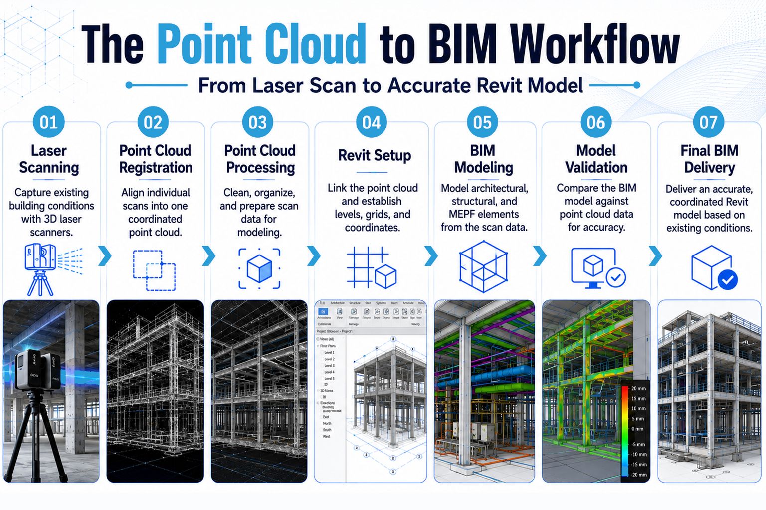
Point cloud registration comes next. Individual scan setups get aligned into one unified coordinate system, using one of three methods:
- Target-based registration uses physical spheres or checkerboard targets placed in overlapping areas. It delivers the highest mathematical certainty, but takes longer to set up in the field.
- Cloud-to-cloud registration relies on an Iterative Closest Point algorithm to automatically align overlapping geometry. It moves fast, but long featureless corridors can cause drift.
- Geo-referenced survey control ties scans directly to State Plane or UTM coordinates using GNSS or total station data. This matters most on large campuses and civil projects.
Once the scans are aligned, the dataset goes through noise filtering. Software strips out pedestrians, moving vehicles, dust, foliage, and reflections, none of which has anything to do with the actual building. Clean data then gets indexed into Autodesk ReCap. This produces .RCS and .RCP files built for fast performance inside Revit. Teams can also export open .E57 files for cross-platform use.
Only after all of that does the point cloud get linked into Revit. Modelers establish a Project Base Point and Survey Point to anchor the data correctly. Levels and structural grids get traced directly from the scan geometry. From there, the team moves into actual parametric modeling. Every finished model runs through Cloud-to-Mesh QA checks before it ships.
How Point Cloud Data Becomes a Revit Model
This is the part that decision-makers care about most. A cloud of disconnected points turns into walls, ducts, and structural columns inside Revit.
Coordinate setup comes first. Scans captured with global geodetic coordinates place the project center far from Revit's internal origin. Import that directly, and Revit's graphics engine can glitch or lose snapping accuracy. Modelers solve this by anchoring a local Project Base Point to a fixed structural reference. The Survey Point stays tied to true global coordinates.
Existing building modeling directly over a full point cloud is nearly impossible. The visual clutter overwhelms the screen. Instead, teams isolate clean slices using Revit's Section Box and view depth tools:
- Horizontal plan slices, cut 25 to 50 millimeters thick at wall height, expose wall cores and door openings without clutter in the way.
- Vertical section slices isolate floor slab thickness, beam depth, and roof pitch.
- 3D section boxes isolate dense mechanical rooms, so modelers can trace complex system routing without visual noise.
Once a slice is isolated, it becomes a precise guide for placing parametric Revit families. This is where Revit point cloud modeling actually happens. Modelers build compound wall assemblies that match the real observed thickness. Brick, insulation, block, studs, and gypsum board get layered exactly as the scan shows. Windows and doors snap directly to the point cloud edges. Structural columns and beams get placed against scan geometry rather than assumed dimensions.
The result is a model built from evidence instead of estimation. That difference is the whole value of point cloud to Revit modeling for firms tired of chasing bad drawings.
How Accuracy Is Maintained During Point Cloud to BIM Conversion
A model can look precise and still be wrong, which is why accuracy relies on a measurable standard instead of a visual impression.
The U.S. Institute of Building Documentation sets that standard through its Level of Accuracy specification. It separates two ideas that get confused constantly. Measured accuracy describes how precise the scanner and registration process were. Represented accuracy describes how closely the finished Revit elements match the point cloud itself. A perfectly scanned building can still produce an inaccurate model if a modeler places elements loosely, and a careful modeler cannot outperform a point cloud with weak registration.
Real buildings also seldom hold perfect right angles. Walls lean, slabs sag, and older structures shift with age. Modeling every millimeter of that drift would bloat file size and slow Revit performance for no real benefit. Instead, teams apply controlled abstraction. Variations within tolerance get normalized to clean geometry. Variations beyond tolerance are modeled explicitly, using sloped slabs or shape-editing point manipulation to capture true physical contours.
Teams perform Cloud to Mesh deviation checks to prove compliance. Scan to BIM experts use software to compare each point in the cloud to the nearest Revit surface and creates a color-coded heat map. Green regions sit within tolerance. Yellow and blue flag minor deviations near the threshold. Red highlights a misplaced or missing element before anyone in design sees it.
| USIBD LOA Tier | Typical Applications | Modeling Impact |
|---|---|---|
| LOA 10 | Early feasibility, site planning, and massing studies | High-level geometry and symbolic elements |
| LOA 20 | Renovation planning, schematic layouts, and space planning | Approximate geometry and element locations |
| LOA 30 | Detailed renovation design, MEPF coordination, and structural verification | Precise geometry for standard commercial BIM |
| LOA 40 | Prefabrication, heritage conservation, and detailed architectural work | Tight alignment and minor deformation modeling |
| LOA 50 | Forensic engineering, monument restoration, and high-precision manufacturing | Sub-millimeter detail with minimal abstraction |
What Can Be Modeled from a Point Cloud in Revit?
Scan to BIM services cover a wide range of building systems. Most firms only need a subset, depending on the project.
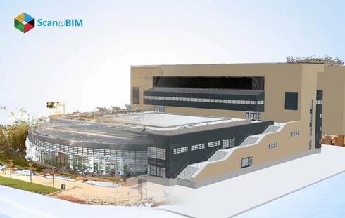
On the architectural side, modelers capture curtain walls and masonry facades. They also model interior partitions, door and window assemblies, staircases, and railings. Historic details like decorative moldings and stone carvings fall into this category too.
Structural modeling pulls out the load-bearing skeleton. That includes cast-in-place and precast concrete, structural steel framing, and foundation systems. Timber framing gets captured where it applies.
MEPF systems tend to be the hardest and most valuable to capture accurately:
- Mechanical: Ductwork, dampers, VAV boxes, diffusers, air handling units, chillers, and rooftop units.
- Plumbing: Hot and cold water piping, sanitary stacks, vent pipes, and stormwater drainage.
- Electrical: Cable trays, busducts, panels, switchgear, transformers, and conduit banks.
- Fire Protection: Main loop piping, branch lines, sprinkler heads, and fire pumps.
Site-focused projects can also extract ground topography, paving, curbs, and retaining walls. Surrounding building massing gets added when the scope calls for it.
Common Challenges in Point Cloud to Revit Modeling
Laser scan data is detailed, but converting it into a usable Revit model still runs into real friction.
File size
Large facilities generate scans ranging from tens of gigabytes to multiple terabytes. Loading that directly into Revit can choke a workstation's RAM and GPU. Teams manage this by segmenting the point cloud into logical zones or floors inside ReCap, then loading only the active work area into the Revit session.
Occlusion
Scanners cannot see through dropped ceilings, furniture, or insulation cladding, which leaves gaps in the data. Modelers rely on domain knowledge to infer continuity across those gaps. Field teams sometimes remove ceiling tiles during the scan to document concealed MEPF routing directly.
Uneven building shapes
Older buildings almost never hold perfect right angles. Walls lean, slabs sag, and corners drift out of square. Revit's native tools assume orthogonal geometry, which makes non-standard surfaces hard to parameterize. Modelers apply controlled abstraction to solve this. Minor deviations within tolerance get normalized to clean axes, while deformations that exceed tolerance get modeled explicitly, using sloped slabs or adaptive components.
Reflective surfaces
Reflective surfaces cause another kind of trouble. Glass, mirrors and polished metal scatter the laser beam, making phantom points that hover outside the real geometry. Processing teams filter these artifacts out during point cloud registration, before the data ever reaches Revit.
Dense MEPF corridors
MEPF corridors bring their own headache. Pipes and conduits overlap so tightly that tracing an individual run becomes guesswork. Experienced modelers cross-reference the point cloud against P&IDs and original construction cut sheets to confirm what they are actually looking at.
Benefits of Creating Revit Models from Point Clouds
None of this process matters if it doesn't change project outcomes, so the numbers behind it are worth looking at directly.
Undocumented existing conditions rank among the leading causes of budget overruns on renovation and retrofit work. Firms skipping reality capture face a 79% chance of cost overruns and a 52% chance of schedule delays. An accurate model built from registered laser scans gives design teams a reliable baseline before drawings even start, and that baseline cuts field change orders and RFIs by up to 25%.
Speed compounds these savings further. Reality capture lets a scan crew document an entire building footprint in a fraction of the time manual surveying requires. Processing that data into a usable model then speeds up pre-construction kickoffs by 30% to 40%, enabling earlier design validation and faster trade contractor onboarding.
A point cloud derived Revit model also functions as a single source of truth for every stakeholder on a project. Architects, structural engineers, and MEP contractors design within the same spatial reference, coordinating clashes and clearances before anyone mobilizes to site.
The value doesn't stop at handoff either. A finished Revit model can carry COBie metadata: equipment serial numbers, warranty dates, and maintenance schedules. Facility managers then use that same model for space planning, budgeting, and emergency response long after construction wraps.
Choosing the Right LOD for a Point Cloud to BIM Project
Two acronyms,LOD and LOA, come up in almost every scope conversation, and mixing them up leads to expensive misunderstandings.
Level of Development
LOD, standardized by the BIM Forum, defines how much detail an element carries and how reliable that information is.
- LOD 100 is conceptual massing.
- LOD 200 is generalized assemblies with approximate size and location.
- LOD 300 represents design development staage with accurate size, shape and location.
- LOD 350 adds cross-trade connection information needed for clash coordination.
- LOD 400 is for fabrication level model detail and accuracy.
- LOD 500 represents a field verified as-built model enriched with operational data.
Level of Accuracy
LOA defines how precisely the modeled geometry aligns with real-world coordinates, independent of how much detail is included. A model can carry low LOD and still be highly accurate, like a simple wall box placed within a tight tolerance. It can also carry high level of detail without high accuracy, if the underlying scan data was noisy or the modeling was loose. Project scope documents need to define both parameters independently, or the deliverable won't match what either party expected.
Matching LOD and LOA to your actual project need keeps cost and schedule under control:
- Site feasibility work typically needs LOD 100 to 200 with LOA 10 to 20.
- Architectural renovation usually calls for LOD 300 with LOA 30.
- MEPF clash coordination needs LOD 350 with LOA 30 to 40.
- Prefabrication requires LOD 400 with LOA 40.
- Facility management deliverables run LOD 500 with LOA 20 to 30, since the priority is asset data, not extreme precision.
Setting these targets before scanning starts prevents scope disputes further. It also keeps your laser scan to BIM services partner accountable to a measurable standard.
Why Choose ScantoBIM.Online for Point Cloud to BIM Services?
High-precision reality capture requires specialized infrastructure, platform expertise, and quality control. ScantoBIM.Online combines all three.
Operating since 2015, the firm has 300+ BIM architects, structural engineers, and MEPF engineers. The team has modeled 100+ million square feet across commercial, historical, educational, and industrial facilities.
AI-driven workflow allows production team to deliver up to 10,000 sq. ft. BIM delivery per day. This speeds up the overall process 50% compared to traditional manual tracing.
Our QC process allows 100+ automated checks per model and Cloud-to-Mesh deviation analysis. The final outputs follow client-specified LOA and LOD targets that follow AIA, IFC, and COBie standards. ScantoBIM.Online also holds ISO 27001 certification.
Architects, engineers, general contractors, and surveying firms can scale Point Cloud to BIM capacity without adding software licenses or full-time staff.
Conclusion
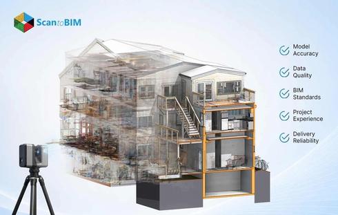
Point cloud to BIM helps teams document existing buildings and carry field conditions into design workflows. Laser scanning captures complex spaces with sub-centimeter level accuracy.
The registered point clouds are then converted to parametric Revit models by the teams. USIBD LOA and BIM Forum LOD provide standards for modeling accuracy and its usability.
AI-powered workflow can speed up modeling time without loss of accuracy. Experienced Point Cloud to BIM providers can help you minimize field rework and control project costs for renovation and retrofit projects.