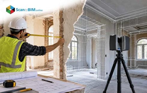





As-built drawings go stale the moment a building gets renovated. Walls move, additions go up, and paper records fall behind. That mismatch surfaces during coordination. New MEP routing collides with a wall that moved without anyone recording it. Rework, change orders, and stalled schedules follow.
Laser scanning services close this gap at the source. Teams capture the structure exactly as it stands today, so the BIM model reflects reality instead of outdated paper. The real question is which capture method gets you there. Each one shapes the accuracy of the model your team builds on.
What Is Reality Capture for BIM?
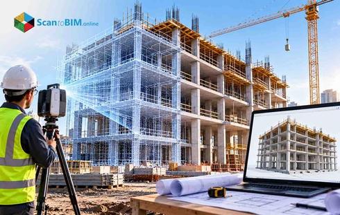
Reality capture for BIM means digitally recording a building's actual condition. That data then builds or updates a BIM model. Laser scanning, photogrammetry, and UAV mapping do this work. Each produces a dense 3D point cloud or mesh that reflects true geometry, not assumed geometry. That point cloud becomes the reference layer inside Revit. Modelers build walls, floors and MEP runs directly against it instead of guesswork.
The process breaks down into three stages:
Data collection
Field teams gather measurements using terrestrial scanners, mobile LiDAR units or UAV-mounted sensors.
Data processing
Raw scans get registered, cleaned and merged into one unified point cloud, typically inside Autodesk ReCap.
BIM modeling
The finished point cloud gets imported into Revit, where teams build BIM elements around it
This structure is what makes point cloud to BIM for existing buildings repeatable. It works for a small retail retrofit or a full campus survey.
How UAV Mapping Improves BIM Data Collection
Drone mapping for construction puts a camera or LiDAR sensor in the air. That single shift changes what a survey team can reach. Roofs, atria, tall façades, and large sites are hard to document from the ground. A drone covers them in minutes. UAV mapping does not just save time. It opens up geometry that ground-based methods would otherwise miss.
Case studies back this up with real figures:
- A BIM-UAV integration study built a 3D model from aerial orthophotos of a lodging property. It reached a horizontal accuracy of 0.0834 meters and a circular error of 0.1265 meters, supporting Level of Detail (LOD) 3 modeling.
- A separate façade survey recorded wall measurement differences near 0.001 meters. Door variance stayed under 0.005 meters against as-built documentation once flight planning and camera calibration were optimized.
- Multi-angle aerial imaging improved geometric accuracy through repeated sampling from different positions. It also reduced the hours a crew would spend walking a site on foot.
Large structures like hangars, where terrestrial access is limited, show this advantage most clearly.
How LiDAR Improves BIM Model Accuracy
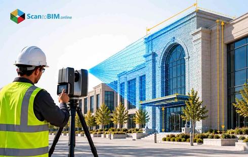
LiDAR scanning for construction planning works on a different principle than cameras. A laser sensor fires pulses and measures the return time. This produces a direct distance reading instead of an inferred one. Low light, uniform surfaces, and dense vegetation all trip up camera-based methods. LiDAR keeps working because it never depends on visible texture or lighting.
The numbers from tested LiDAR systems tell the story:
- Fine object dimensions measured by LiDAR varied between negative two and positive two percent relative to conventional measurement. Residual deviations typically sat in the low millimeter to low centimeter range.
- A multi-angle LiDAR BIM modeling workflow produced horizontal and vertical RMS deviations below 0.05 meters. This met RICS measured survey classes and ISO 19650 requirements.
- That same workflow improved façade completeness by roughly 20 percent compared with single-sweep scanning.
- Mobile LiDAR mapping systems reached accuracy within a few centimeters across entire urban blocks. That outperformed photogrammetric point clouds in the same environments.
This reliability is what lets modelers snap Revit elements directly to scan data. It gives teams confidence when building point cloud to BIM for existing buildings against tight accuracy targets.
How Photogrammetry Supports BIM Modeling
Photogrammetry BIM modeling takes a different route to the same destination. Instead of measuring distance directly, it reconstructs geometry from overlapping photographs using structure-from-motion algorithms. This approach works well on façades, roofs, and heritage structures, where visual texture and surface detail carry real design value. A laser captures the shape of a carved cornice. A photograph captures the shadow lines and material texture that show what it actually looks like.
Research on wall reconstruction from photogrammetric meshes confirms this is now a standard input for BIM modeling. UAV oblique imagery routinely supplies original survey data for existing buildings. That same research flags real limits worth planning around:
- Noise and missing data inside the point cloud can complicate the reconstruction of solid walls and other elements.
- Photogrammetric models in comparative testing carried façade height errors averaging 0.62 meters. Peak errors reached 1.43 meters in harder cases.
- Total volume errors landed near five to six percent in the same testing.
Photogrammetry earns its place in many workflows, but precision can slip where vertical accuracy and volume calculations matter most. Heritage projects show it at its strongest. A documented HBIM project at the Arco della Pace in Milan combined terrestrial and UAV photogrammetry. The goal was capturing decorative complexity that a pure LiDAR scan would likely flatten. The resulting model supported extended reality applications for public engagement with the structure.
LiDAR vs UAV Photogrammetry for BIM
Choosing between LiDAR and photogrammetry comes down to what the project actually needs. LiDAR measures distance directly, so it holds up regardless of lighting or surface texture. Photogrammetry depends on strong image overlap and visible texture. Performance drops on blank walls, glass, or poorly lit interiors as a result.
Here is how the two compare on accuracy:
- UAV LiDAR delivered higher relative accuracy than UAV photogrammetry in one built-environment study , particularly for volumetric measurements.
- A separate comparison recorded mean façade height errors of 0.69 meters for LiDAR. UAV photogrammetry recorded 0.62 meters in the same test case.
- Total volume errors landed near six and seven percent respectively, showing performance can converge when methodology is handled carefully.
Here is how they compare on cost and deployment:
- UAV photogrammetry uses less expensive equipment and can cover large areas quickly which makes it perfect for tight budgets or short deadlines.
- LiDAR generally holds the accuracy edge, especially for volumetric work.
- Most BIM teams route structural and MEP coordination through LiDAR, then reserve photogrammetry for visualization and façade documentation.
Applied well, these two methods are less a rivalry and more a division of labor. The next question is what happens when you stop choosing and combine them instead.
Combining UAV, LiDAR, and Photogrammetry for Better BIM Accuracy
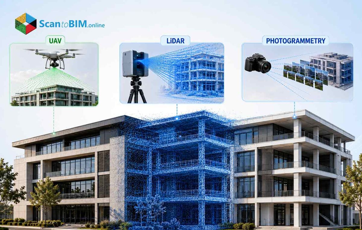
None of these three technologies has to work alone. The strongest projects usually blend them. LiDAR anchors the geometry on low-texture surfaces and in difficult lighting. UAV photogrammetry adds high-resolution visual context for façades and roofs. UAV-mounted LiDAR extends coverage across a campus while holding accuracy steady at scale.
A 3D campus mapping study puts real numbers behind this combination:
- Researchers co-registered LiDAR point clouds against photogrammetric reconstructions from nadir and oblique drone passes. Mean point spacing stayed under 5 centimeters.
- Façade completeness rose to 95 percent.
- Surface deviation against CAD references dropped from 12.4 centimeters with nadir-only imagery to 6.3 centimeters combined. That is roughly a 30 percent improvement.
Urban LiDAR-BIM research tells a similar story. Multi-angle LiDAR acquisition paired with semantic mapping and careful registration. Together they cut horizontal RMS errors roughly in half compared with single-sweep baselines. Façade completeness rose by at least 20 percent in the same study. Aligning LiDAR and photogrammetry inside one coordinate frame lets modelers pull structural precision from laser data. They pair it with visual richness from imagery. The result is more complete as-built BIM modeling services for complex sites.
From Reality Capture to BIM: The Complete Workflow
Every method above feeds into the same end-to-end process. Understanding that sequence separates a clean BIM deliverable from a messy one. The workflow runs through five stages, regardless of which capture technology leads:
Planning
Teams define accuracy targets and choose between LiDAR, UAV mapping, or photogrammetry. They map scan positions or flight paths around control points.
Acquisition
Crews carry out laser scanning services on-site utilizing either terrestrial or mobile units or they conduct UAV missions for aerial capture.
Processing and registration
Every scan or image set gets aligned into one unified point cloud inside software like Autodesk ReCap.
Modeling
The reference data gets linked into Revit and levels and grids get established. Structural and MEP elements get built by snapping directly to captured geometry.
Validation
Teams run QA and QC checks, then pull 2D drawings and schedules. Deliverables include the Revit model, IFC exports and the registered point cloud.
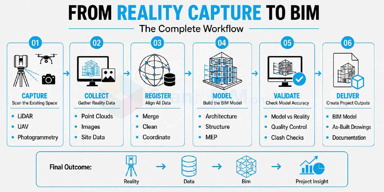
The modeling stage is where point cloud to BIM for existing buildings actually becomes a working model. Every stage keeps the digital model traceable back to the physical asset, supporting reliable updates down the road.
Applications of UAV, LiDAR, and Photogrammetry in BIM
A model built through reality capture only matters if it holds up across how different teams actually use it. The applications vary widely depending on project type and phase:
Renovation and adaptive reuse
Laser scanning and photogrammetry register existing geometry with high accuracy and cut survey time. The resulting base models support clash detection, sequencing, and quantity take-off.
Facility management
Integrated LiDAR and BIM workflows produce georeferenced digital twins for buildings and city blocks. Research cited earlier showed sub-decimeter RMS deviations and strong façade completeness.
Campus and portfolio operations
Campus-scale UAV and LiDAR mapping generates 3D meshes for asset tracking and navigation. It also supports maintenance planning across multiple buildings.
Heritage conservation
Photogrammetry BIM modeling paired with LiDAR scanning documents historic structures with precision and visual fidelity. The Arco della Pace project shows this clearly.
Structural inventory
UAV photogrammetry paired with BIM has assessed the stability of large-span buildings like hangars.
Reality capture for BIM scales from a single façade up to a full structural assessment. The accuracy you get depends heavily on which method drives the survey.
| Parameter | UAV Mapping | LiDAR | Photogrammetry | Combined Workflow |
|---|---|---|---|---|
| Accuracy Level | Moderate, depends on flight altitude and camera resolution | High, typically 3–15 mm depending on scan type | Moderate, typically 1–3 cm | High, often reaches LOD 300–400 |
| Best Use Case | Large sites, rooftops, hard-to-reach areas | Structural detail, MEP coordination, retrofit planning | Facade texture, historic detail, visual documentation | Full-building capture requiring precision and visual context |
| Data Output | Aerial imagery, orthomosaics, sometimes point clouds | Dense point clouds with precise distance data | 3D mesh with photorealistic texture and color | Registered point cloud combining geometry, texture, and aerial coverage |
| Equipment Cost | Moderate, drone plus camera or sensor payload | High, specialized scanning hardware | Low, standard camera equipment sufficient | High, requires multiple capture tools and processing software |
| Processing Time | Fast for imagery; longer for 3D models | Fast, direct point cloud generation | Slow, requires image matching and triangulation | Longest, due to multi-source data registration |
| Lighting Dependency | Dependent on daylight and weather conditions | Independent, works in low light or darkness | Highly dependent on consistent, good lighting | Reduced dependency since LiDAR compensates for poor lighting |
| Ideal Project Type | Infrastructure, large campuses, industrial sites | MEP retrofit, structural clash detection | Heritage restoration, facade documentation | Complex renovations, multi-discipline coordination projects |
How Accurate Can a Reality-Capture-Based BIM Model Be?
The honest answer depends on the technology, the control points, and how disciplined the registration process was. Published research still gives a clear picture of what to expect from each method:
Terrestrial LiDAR
Millimeter to centimeter range, with dimension deviations of negative two to positive two percent against traditional methods. RMS deviations stay below 0.05 meters, meeting RICS and ISO 19650 standards.
UAV photogrammetry
Centimeter to decimeter range, with horizontal RMSE of 0.0834 meters recorded for LOD 3 work. CE reached 0.1265 meters, and local façade differences ran as tight as 0.001 to 0.005 meters under favorable conditions.
Hybrid LiDAR and photogrammetry
The strongest results. Combined capture workflows frequently hit LOD 300 to LOD 400, sufficient for construction documentation and clash detection.
These figures translate directly into practical BIM terms. Levels of Accuracy in the 30 to 50 range define common construction tolerances. These run from a few centimeters up to a few tens of centimeters. Documented LiDAR and UAV photogrammetry performance falls comfortably within that range. Getting there consistently still comes down to disciplined control networks and thorough QA, not the sensor alone.
Conclusion
Reality capture is no longer optional for teams that need dependable as-built BIM modeling services. LiDAR delivers the tightest geometric accuracy. Photogrammetry adds visual richness for façades and heritage work. UAV mapping extends both across sites too large or inaccessible to walk.
The research is consistent on one point: combined workflows outperform any single method. They cut surface deviation and boost façade completeness well beyond what one sensor achieves alone. For AEC teams weighing renovation, coordination, or facility management work, the choice is not LiDAR or photogrammetry. It is picking the right blend for the accuracy your project actually requires.