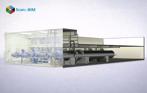
Oil and gas facilities rank among the most complex industrial environments on earth. Industrial plants carry thousands of pipe runs, pressure vessels, rotating equipment and instrument loops across every deck and elevation. Accurate documentation of these assets directly determines the outcome of every retrofit, turnaround, and expansion project.
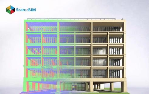
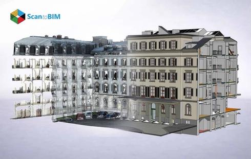
The Point Cloud to BIM workflow converts this documentation challenge into a structured digital process. Laser scanners sweep across plant areas and record millions of spatial data points. Skilled BIM modelers then trace that point data into intelligent 3D models. Each element carries geometry, material specifications, P&ID tags, and operational metadata.
The workflow replaces outdated 2D drawings with verified spatial data. Field teams in the past encountered discrepancies between paper records and actual plant configurations. Those discrepancies generated costly rework, permit delays, and safety exposures. Point Cloud to BIM closes that gap permanently.
This blog covers the full process, applications, challenges, and best practices that define successful Point Cloud to BIM execution in oil and gas projects.
Why Oil and Gas Facilities Require Accurate BIM Models
A single design conflict in a piping modification triggers an unplanned shutdown. That shutdown costs the operator millions in lost production and emergency labor. Accurate BIM modeling for oil and gas plants provides engineers with verified piping geometry data before fabrication begins.
Oil and gas assets accumulate decades of undocumented modifications. Valve additions, rerouted headers, added instrument tapping points, and structural reinforcements all alter the physical plant. The BIM model captures the actual building condition and gives all project stakeholders a single verified reference for every decision.
Regulatory requirements also demand accurate documentation. Safety cases, inspection records, and process hazard analyses all draw from asset information. A BIM model aligned to as-built conditions supports these requirements with verifiable spatial data. Facility managers, process engineers and safety officers all access the same dataset. This alignment eliminates information gaps that traditionally cause coordination failures.
How Point Cloud to BIM Works for Industrial Plants
The Point Cloud to BIM workflow follows six structured stages. Each stage builds on the previous one to deliver a verified, data-rich BIM model.

Stage 1: Field Scanning
Scanner operators position instruments across the plant at pre-planned stations. The equipment emits laser pulses and records XYZ coordinate returns for every surface within range. A mid sized process unit of 5,000 square metres requires between 80 and 150 scan stations for complete coverage.
Stage 2: Point Cloud Generation
Raw scan data forms a three-dimensional surface map of every structure and piece of equipment. This map is the point cloud, the spatial foundation of the entire workflow. The system records pipe diameters, flange positions, structural steel centroids, and equipment boundaries simultaneously.
Stage 3: Data Registration
Processing software aligns all scan stations into one unified coordinate system. Overlapping zones between adjacent stations lock the cloud into accurate spatial positions. The registered cloud represents the full facility geometry as a single, verified dataset.
Stage 4: BIM Modeling
Modelers open the registered cloud in BIM authoring software. They trace pipes, structural steel, equipment bodies, valves, cable trays, and instrumentation from the point data. Every element receives metadata including nominal diameter, schedule rating, insulation type, and P&ID tag number.
Stage 5: Isometric Extraction
BIM software generates pipe isometrics directly from the model geometry. Each isometric shows exact pipe routing, flange positions, bend angles, and spool lengths. Fabricators manufacture spools off-site using these verified drawings as their primary reference.
Stage 6: Validation & Delivery
QA engineers overlay the completed model against the original point cloud. Spatial deviation reports flag any element that falls outside the project accuracy tolerance. Teams correct deviations before delivering the final model and associated isometric drawing sets.

Role of 3D Laser Scanning in Oil and Gas Facilities
Scanning technology sets the accuracy ceiling for the entire BIM workflow. The Types of Laser Scanners available for industrial use divide into three main categories, each suited to different plant environments and geometry types.
1. Phase Scanners
Capture interior environments at ranges up to 80 metres with sub-millimetre accuracy. Control rooms, compressor buildings, and congested pipe rack structures suit this scanner type best.
2. Time of Flight Scanners
Cover large outdoor areas at ranges exceeding 300 metres. Tank farms, flare structures, and long pipeline corridors all fall within this scanner category.
3. Structured Light Scanners
Resolve complex small-bore fittings, nozzle geometries, and manifold assemblies where very fine detail matters for fabrication drawings.
Scanning teams plan station positions to achieve full coverage with at least 30% overlap between stations. They capture every pipe rack level, equipment skid, and structural bay. Crossing pipe headers, control valve stations, and instrument tapping points all appear in the final cloud. This spatial completeness gives modelers the data they need for accurate isometric extraction and flange alignment documentation.
In oil and gas environments laser scanning removes the requirement for manual measurements in tight or hazardous spaces. Surveyors capture pipe rack geometry from a safe standoff distance. The scanner records pipe diameters, elbow positions, and support locations with equal accuracy from any angle.
Benefits of Point Cloud to BIM for Oil and Gas Projects
Point cloud to BIM modeling services deliver measurable gains across every project phase from the design table through the fabrication shop and into the full operational lifecycle.
Dimensional Accuracy
The workflow removes human measurement error entirely. LOD 400 models stay within ±3mm of actual plant geometry, covering the full facility area.
Speed of Data Capture
Scanner teams complete data capture of a full process unit in two to five days. Manual survey teams require weeks for equivalent area coverage.
Isometric Extraction
Modelers generate pipe isometrics directly from the BIM model. Each isometric carries verified spool lengths, bend angles, and flange face orientations for fabricators.
Flange Alignment
The model records the exact rotational position of every flange face. Fabricators prepare matching bolt hole patterns and gasket faces at the correct orientation.
Pipe Spooling Accuracy
BIM-derived spool drawings include cut lengths, end preparations, and material grade specifications minimizing fabrication waste and on-site fit-up time.
Lifecycle Value
The as-built model supports future turnarounds, regulatory inspections, and plant expansions. Every downstream project draws from the same verified spatial dataset.
Applications in Refineries, Pipelines, and Processing Plants
As-built BIM industrial facilities data serves distinct needs across each oil and gas asset type. The workflow applies from upstream production facilities through to downstream processing and distribution.
Refineries
BIM models map every pipe rack, reactor vessel, heat exchanger, and pump base across the plant. Shutdown planners extract pipe spool lists from the model weeks before any outage. Fabricators produce matched spool sets in advance. Installation crews arrive at the turnaround with pre-fabricated components that fit the verified plant geometry.
Pipelines
Surveyors scan above-ground pipeline sections to verify alignment, coating conditions, and support spacing. Scan to BIM for oil and gas plants workflows produce accurate corridor models for pipeline integrity management. Engineers model proposed tie-in spools within the existing pipeline geometry and confirm fit before mobilizing field crews. This preparation eliminates the costly surveys that traditionally precede every pipeline modification.
Processing Plants
BIM models of processing facilities show complete MEP systems, equipment placements, and structural grids. Engineers model replacement pumps, compressors and heat exchangers within the plant's spatial envelope. The model confirms footprint fit, nozzle orientation and piping connection geometry before procurement and fabrication begin.
Offshore Platforms
Laser scanning captures platform decks, pipe spools, structural members, and module layouts. The resulting models support topside modifications and life extension projects without repeated offshore mobilizations for additional surveys.
Digital Twin Programs
BIM models serve as the geometric backbone of digital twin systems. Operators attach live sensor feeds to BIM elements and monitor equipment condition through the model interface in real time. This connection turns static documentation into a dynamic operational tool.
Challenges in Oil and Gas Scan to BIM Projects
Industrial scanning projects present real technical challenges. Planning teams must address these challenges directly before mobilisation to protect project timelines and deliverable quality.
1. Reflective Surfaces
Insulated pipes, polished vessels, and stainless-steel equipment scatter laser returns. Scanning teams mitigate this by adjusting scan angles and placing diffuse reference targets on problem surfaces before scanning begins.
2. Congested Pipe Racks
Tightly packed headers create occlusion zones where the scanner cannot see behind adjacent lines. Teams add supplementary scan stations at mid-rack elevations to capture geometry hidden from standard positions.
3. Massive Dataset Volume
Full-refinery scans exceed 500 GB of raw data. Processing infrastructure requires high-memory workstations and fast NAS storage arrays. Teams partition datasets by process unit to manage computational load and enable parallel processing.
4. P&ID Correlation
Modelers cross-reference point cloud geometry against P&IDs to confirm every bypass loop, instrument tapping, and control valve appears correctly in the BIM model. This time-intensive step prevents costly specification errors in fabrication.
5. Legacy Documentation Gaps
Facilities modified over decades carry conflicting drawing records. BIM modelers treat the scan data as the authoritative source and verify every element directly against the point cloud geometry rather than historical documents.
6. Multi-Discipline Coordination
Structural, piping, and instrumentation teams work on shared model environments. Clear LOD targets, naming conventions, and revision protocols prevent conflicts between concurrent modeling workstreams across all disciplines.
MEP and Piping Coordination in Industrial BIM Models
Oil and gas facilities route piping, utility lines, electrical cable trays, instrument tubing, HVAC ducting, and firefighting mains through shared structural corridors. Every system competes for the same spatial envelope. Conflicts between systems cause the most expensive rework incidents in industrial construction.
BIM models assign each discipline to a dedicated workset. Coordination software runs automated clash detection across all worksets simultaneously. The algorithm flags every geometric intersection between pipes, cables, ducts, and structural members. Engineers receive a prioritised clash report and resolve each conflict in the model environment before any fabrication drawings leave the office. Modern workflows often integrate Scan to BIM for MEP Coordination to accurately capture existing site conditions that are accurately reflected in the digital model before clash detection begins.
Modelers reroute conflicting lines within the BIM environment. The rerouting process respects pipe stress analysis requirements, insulation clearance standards, and maintenance access lane widths. Every resolved route updates the isometric drawing set automatically. This keeps fabrication documents aligned with the coordinated model throughout the project.
Flange alignment in coordinated piping models carries particular importance for tie-in accuracy. Process engineers specify the required rotational position of each flange face in the BIM element properties. The fabrication team reads those rotational values from the isometric and prepares matched bolted connections. Correct flange face orientation eliminates field-cut corrections at tie-in during turnaround windows.
Accuracy and LOD Requirements for Oil and Gas BIM
The Level of Development framework defines the detail and spatial accuracy required at each project phase. Oil and gas projects assign LOD targets based on the intended use of the model deliverable. Selecting the correct LOD directly affects project cost, schedule, and downstream model usability of the model deliverable.
LOD 200 to LOD 500 Oil & Gas BIM Requirements at a Glance
| LOD Level | Project Phase | Key Deliverable | Pipe Detail |
|---|---|---|---|
| LOD 200 | Conceptual Layout & Feasibility, General arrangement and equipment zones | Plot plans, area sketches | Approximate cylinder routing |
| LOD 300 | Detailed Design Review, Pipe routes on exact centerlines from point cloud | Structural drawings, MEP layouts | Nominal diameter, routing path |
| LOD 350 | Construction Coordination, Spool break points, hanger plates, anchor bolt patterns | Pipe isometrics, spool sheets | OD, wall thickness, flange standard |
| LOD 400 | Pipe Spool Fabrication, Cut lengths, bevel preps, weld joint sequences | Fabrication drawings, MTO packages | Insulation, heat trace, supports |
| LOD 500 | As-Built: Facility Management & Maintenance, Verified as-installed record, field deviations captured | Regulatory record, inspection basis | Full pipe specification + installed condition |
Piping systems in oil and gas facilities target LOD 350 or higher for spool fabrication work. At this level, every pipe segment carries exact outer diameter, wall thickness, insulation type, and flange standard. The model supports direct isometric extraction and off-site spool manufacturing from verified parameters.
Structural elements reach LOD 300 for spatial coordination and LOD 400 for detailed fabrication models. Equipment items reach LOD 350, including nozzle orientations, foundation bolt patterns, and access clearance zones. Research industries studies indicated that scanned models at this accuracy level reduce rework incidents by 34% across sampled industrial projects.
Point cloud to BIM for industrial facilities delivered at LOD 500 give facility managers a verified record of every installed element. Maintenance crews access the model to plan replacements and upgrades. The current, accurate model reduces the need for additional site surveys during every phase of operations, returning significant time and cost savings to the asset owner.
Safety and Compliance Considerations in Laser Scanning
Oil and gas facilities classify process areas under ATEX and IECEx zone ratings. Zone 1 areas contain flammable atmospheres intermittently. Zone 2 areas carry flammable atmospheres only under abnormal conditions. Standard commercial laser scanners carry electrical components that present ignition risk in these environments.
ATEX-certified scanners carry Ex d (flameproof) or Ex ia (intrinsically safe) ratings. These certifications confirm that the scanner enclosure prevents ignition of the surrounding classified atmosphere. Scanning supervisors verify the zone classification map before deploying any equipment in process areas. Equipment such as the Leica BLK360 and Faro Focus with Ex-rated configurations meet Zone 1 and Zone 2 operational requirements for oil and gas environments.
- Hot Work Permit: Teams submit pre-work documentation including scanner Ex certificates, job safety analysis forms, and emergency response plans before Zone 1 area entry.
- Gas Monitoring: A calibrated gas monitor operates continuously during scanning sessions to detect hydrocarbon accumulations above the lower explosive limit at all times.
- Supervisor Certifications: Scanning supervisors must hold current Confined Space Entry and H2S awareness certifications for all process area field scanning sessions.
- PPE Requirements: Intrinsically safe communication devices and arc-flash-rated personal protective equipment form the minimum equipment list for every classified zone session.
BIM modeling for oil and gas plants further supports safety compliance throughout the facility lifecycle. Engineers extract 3D clearance checks from the model to confirm that escape route widths, safety shower coverage areas, and firewater monitor positions remain accessible after any plant modification. This documentation supports OSHA compliance and local safety authority requirements across all jurisdictions.
Best Practices for Point Cloud to BIM in Industrial Facilities
Successful industrial plant modeling projects share a consistent set of execution practices. Teams that follow these practices achieve higher accuracy, shorter timelines, and fewer revision cycles.
1. Define Project Scope Precisely Before Mobilisation
Identify all process units, pipe rack sections, and equipment items the scan must cover. Set LOD targets for each area in a written project execution plan agreed upon by all stakeholders before any scanner mobilises to site.
2. Match Scanner Technology to Zone Classification
Deploy ATEX rated instruments in all classified zones without deviation. Select phase-based scanners for congested indoor areas and time-of-flight scanners for large outdoor structures and long pipeline corridors.
3. Plan Scan Stations for Minimum 30% Overlap
Target at least 30% overlap between adjacent stations. This overlap enables accurate registration and eliminates gap zones in the final dataset that would otherwise require a costly return mobilisation to the site.
4. Process Raw Scan Data Within 48 Hours of Field Capture
Early processing reveals coverage gaps while the scanning team remains on site to fill them. Processing delays push gap-filling into a separate mobilisation, multiplying travel and access costs for the project owner.
5. Apply ISO 19650-Aligned Naming From the First Modeling Session
Consistent element names support downstream information management, clash detection, and asset register population. Retrofitting naming standards after modeling is complete costs far more time than applying them from the outset.
6. Conduct a Formal Multi-Discipline Model Review at LOD 300
Structural, piping and instrumentation teams review the model jointly before advancing to LOD 400 fabrication detail. Early review catches coordination conflicts at the lowest possible correction cost in the project lifecycle.
7. Extract All Isometrics Directly From the BIM Model
Generate every pipe isometric directly from model geometry. This eliminates manual drafting errors and keeps all isometrics synchronized with any model updates made during the construction or turnaround execution phase.
Cost Considerations for Oil and Gas BIM Projects
BIM for industrial plants project costs divide across three categories. Understanding each category helps project owners forecast budgets and evaluate return on investment accurately.

A qualified scan to BIM service provider structures project costs around scan area, modeling scope, and LOD requirements. A mid sized process unit project ranges from $25,000 to $80,000 depending on coverage area and deliverable complexity. Outsourcing BIM modeling to specialist teams reduces the total investment compared to building permanent in-house capability.
The return on these investments appears across the project lifecycle. Verified spool drawings reduce pipe fabrication scrap rates and eliminate re-fabrication costs. As-built models remove survey cost from every future modification project at the facility. Clash detection in the BIM environment costs a fraction of the equivalent rework correction performed in the field during a live turnaround window.
Choosing the Right BIM Partner for Oil and Gas Projects
Plant retrofit and upgrades projects demand a BIM partner with direct industrial experience. Architectural BIM firms lack the piping knowledge, ATEX awareness, and process plant familiarity that oil and gas work requires. Evaluating three core capabilities before contract award protects both project quality and delivery schedule.
1. Industrial Point Cloud Experience
Refinery and petrochemical datasets contain geometry that general BIM teams rarely encounter. Pipe rack headers, exchanger bundle pull zones, and vessel nozzle schedules require specialist modeling knowledge and P&ID literacy that only comes from direct industrial project experience.
2. ISO 19650 Alignment
A partner operating ISO 19650-aligned quality systems governs deliverable naming, revision control, and model validation. This alignment protects information integrity throughout the project lifecycle and into long-term asset management across the facility's full operational lifespan.
3. Delivery Capacity for Turnaround Schedules
The BIM partner must mobilise sufficient modeling capacity to deliver spool drawings, clash reports, and as-built models within defined shutdown windows. Review project references that confirm industrial delivery performance and LOD 350–500 achievement rates across comparable projects.
Laser scan to BIM services from a specialist provider deliver faster turnarounds, higher accuracy, and models that meet industry specific requirements from day one of the project. Outsourcing to a global BIM team gives project owners access to skilled modelers at competitive rates. In-house engineering teams focus on process design and facility management rather than documentation tasks maximizing the value of every team member's expertise.
Conclusion
Point Cloud to BIM gives oil and gas facilities a verified, data-rich digital record of their physical assets. The workflow captures spatial reality through laser scanning and converts that data into intelligent BIM models at defined LOD levels. Engineering teams use those models for isometric extraction, flange alignment verification, spool fabrication, clash detection, and regulatory compliance documentation.
The process supports every phase of the facility lifecycle. Modification planning, turnaround execution, equipment replacement, and long term asset management all draw from the same verified model. Research data confirms that organizations adopting this workflow achieve measurable reductions in rework incidents and fabrication errors. They also experience lower unplanned maintenance costs during the first three years of operation.
Selecting a BIM partner with industrial experience and ISO 19650 aligned quality systems determines the quality of every deliverable. Point cloud to BIM oil and gas facilities workflows stand as a proven, effective method for managing the spatial complexity and operational risk of every oil and gas asset type worldwide.